A Mini Monitor for a Pi
This post outlines how I used a small 2 inch display as a monitor for my pi. Where it can display tty terminals and X desktops and applications as if it was a normal screen connected over hdmi.
My overall goal is to have a sort of handheld “console” that I can connect a keyboard to and use as a normal computer. This post implements the display functionality needed to fulfill part of the goal.
I lay out the steps needed for interacting with the display over spi and the issues I encountered trying to use it like a monitor. The end result is a system service that runs on startup, consuming 2.5 mb of ram and ~2% of the CPU. It also respects the X display power management system (dpms) to save on battery life by going to sleep and turning the backlight off.
an x screensaver
code editing
web browsing
using the terminal
Source code for the display mirroring program.
Below I outline the journey of how I created the mirroring program. At the end I also include instructions so you can set up your hardware in the same way.
Hardware
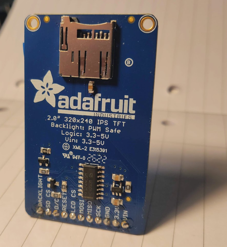
I have a 2 inch 240x320 ips tft display sold by adafruit, driven by an ST7789 controller by Sitronix. It cost around £20 when I bought it.
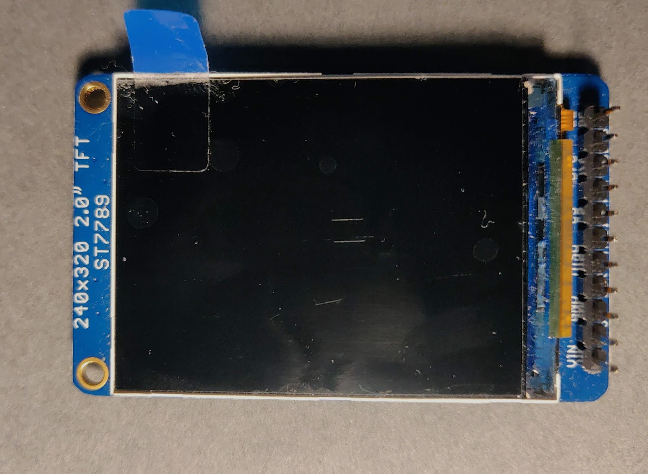
The info on how to interact with the display with commands and data, is in the display datasheet. Which was my source of information for writing the code which interacts with the display. Adafruit also has some docs, but they are unspecific and don’t say very much.
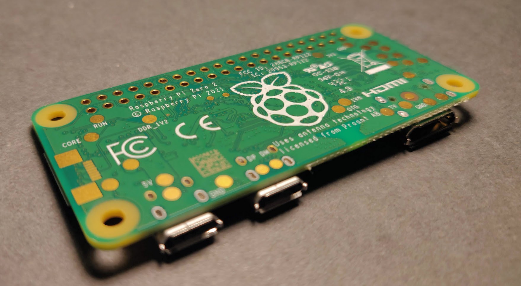
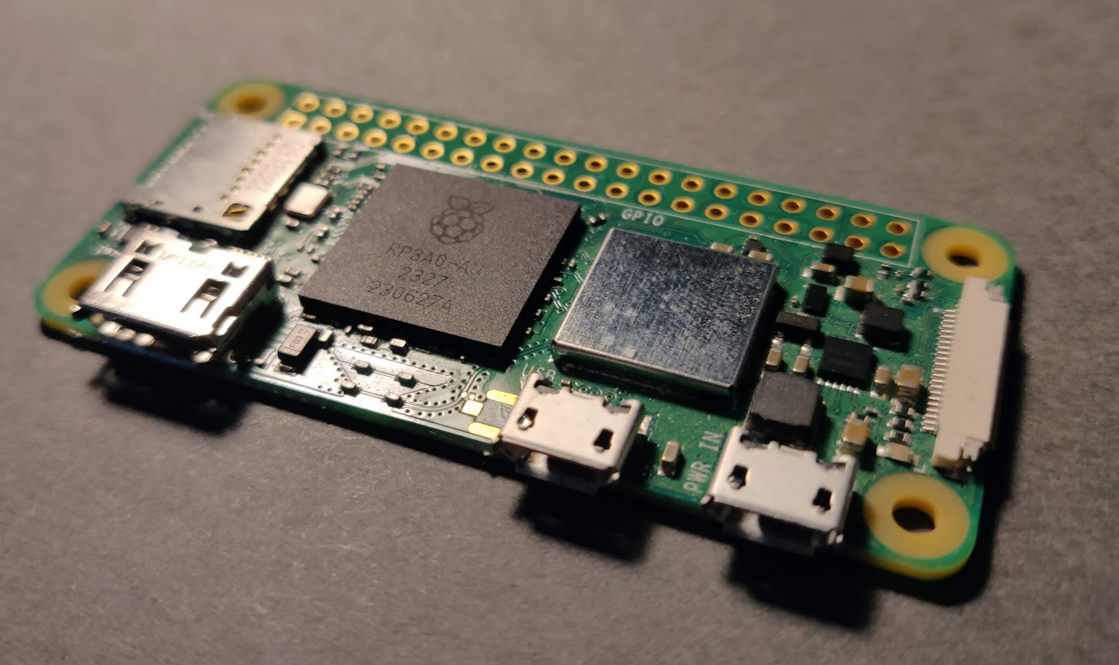
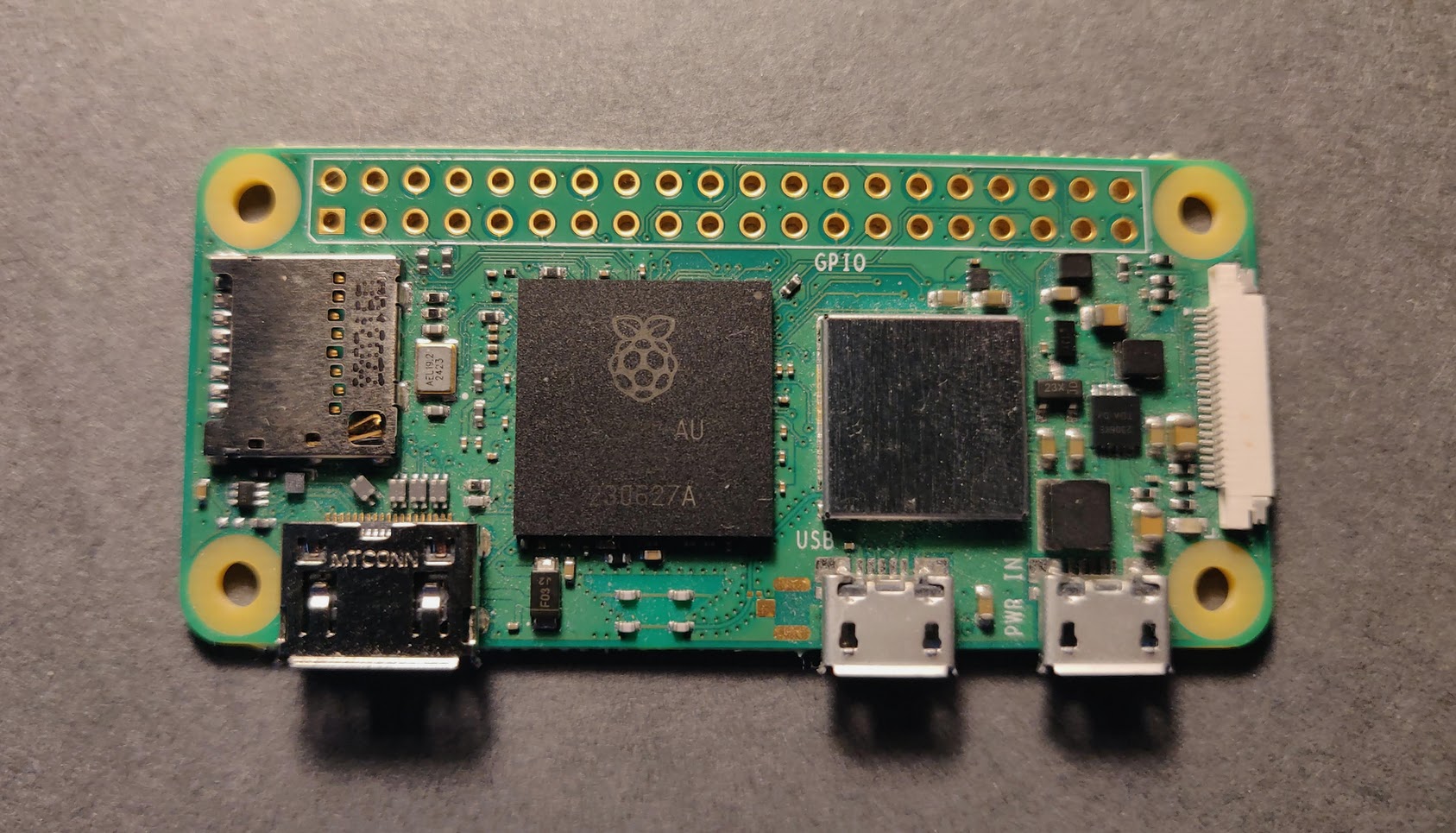
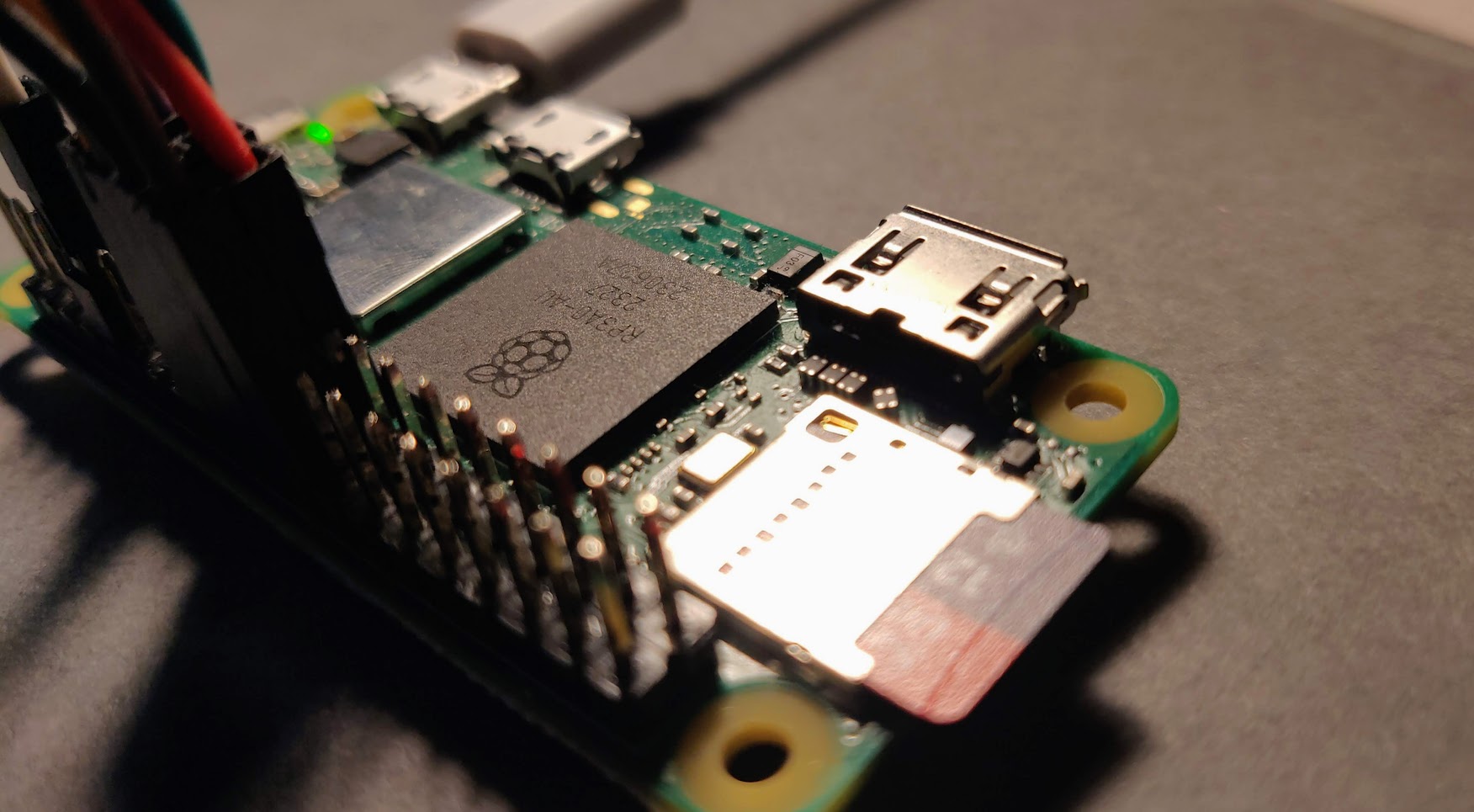
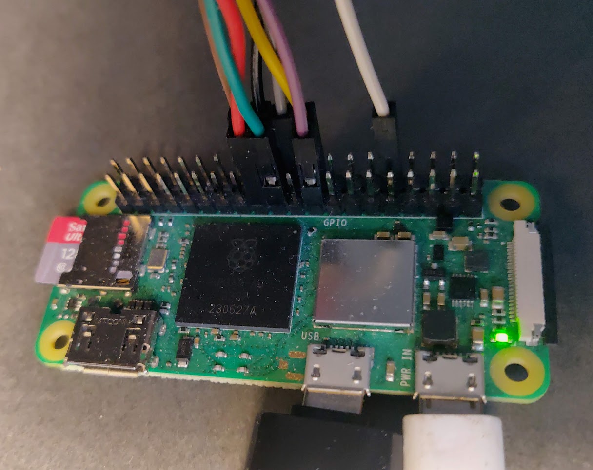
For a computer, I’m using a Raspberry pi zero 2 w. It costs around £15. This has the same processor as the pi 3, but only 500mb of ram. The software/setup should work with any pi.
None of the pins came with headers presoldered for the pi and the display, so to make it easier to wire and prototype I recommend soldering on headers and using dupont wires for connecting the circuit together.
Wiring
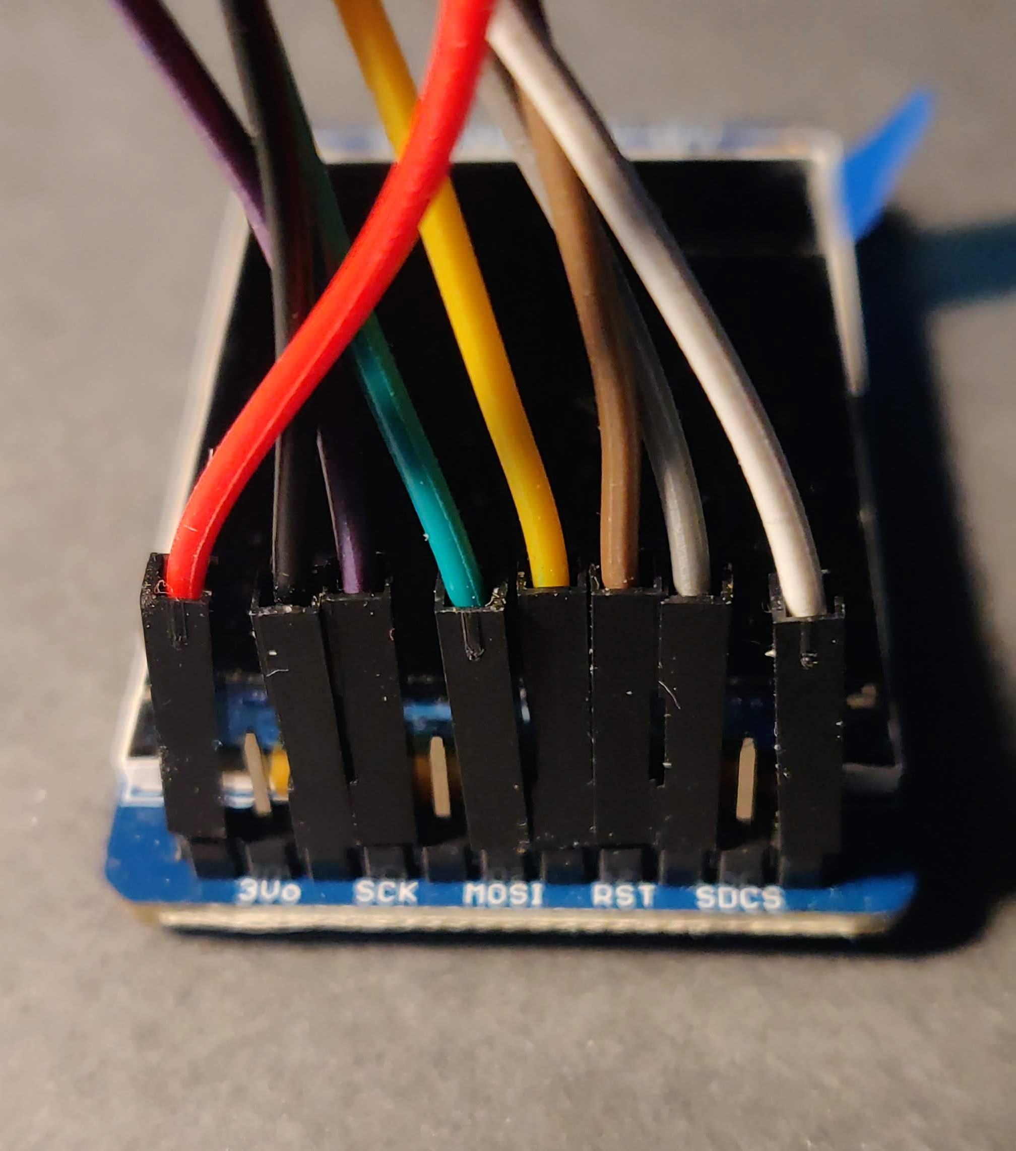
I wired the display with 8 wires, we have two wires for power, three for spi, and three for the data/command, backlight, and reset.
Spi uses one pin for chip select, which tells the device when to listen to the data and clock lines (This allows multiple devices to share the same spi wires). It uses one pin for a clock, which synchronises communication, and two pins for back and forth communication (MOSI/MISO). It seems the adafruit display only uses the MISO pin for reading from the sd card on the board. This means none of the ST7789 read commands can be used, but it means we have one less wire to worry about.
The data/command wire is used in conjunction with spi to tell the display if the data being send is a command (low) or the data (high) associated with it.
There is a reset pin, that completely hardware resets the display. This is optional, as there is also a software reset command.
Finally there is the backlight pin, which determines the brightness of the display. The backlight is either on (high) or off (low). Brightness levels can be controlled using pulse width modulation (pwm). This means the backlight is rapidly turned on and off to simulate different brightness levels. This is supported by the pi hardware.
Communicating With the Display
The display has a list of commands that it accepts, and arguments that can be passed with those commands. Each command is a byte. Some commands take any number of arguments. To communicate with the display the data/command pin is pulled low, a bytes is sent for the command, then the data/command pin is pulled high and the argument data is sent.
For example the command to set the column address takes 5 bytes.
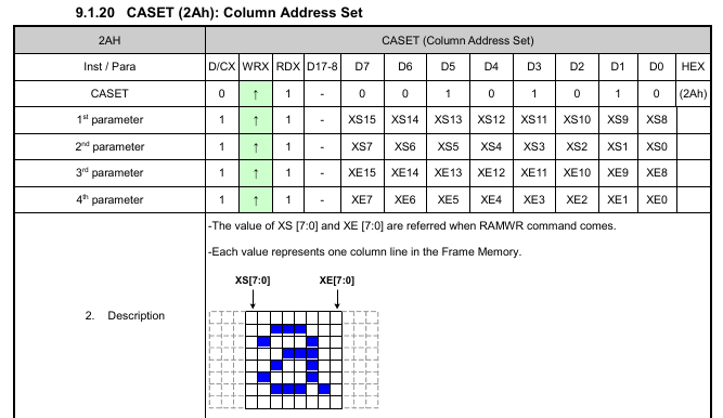
Where the command has a hex value of 2A, and the start and end address are
two bytes each.
Before drawing can commence, the display needs to be taken out of sleep mode; display mode must be enabled; and the column and row addresses must be set. Finally a draw command followed by the colour data will make colour appear on the display. I experimented a while trying to get the monitor to show something.
After some tinkering, I could address specific sections of the display properly.
The way display can be addressed can be modified with commands. How an image is show can be mirrored and flipped and rotated along any direction. The format of the colour data sent to the display can also be modified, such as the data’s endianness and colour order, as well as the colour depth.
The display supports 12, 16 and 18 bit colour data.
pixel size | r-g-b bits
-----------------------
 12 bits   | 4-4-4
 16 bits   | 5-6-5
 18 bits   | 8-8-8
Where 18 bit only uses the first 6 bits of each byte.
Display C Api
I bundled up the code for interacting with the monitor into a c api so that I could more easily write programs that used the display and encapsulates it’s state into a nice wrapper with some sanity checks.
One thing the library does is to break into chunks the data sent to the display. The spi device has a max buffer of 65536 bytes (default is 4096), so any writes to the buffer greater than that are quietly discarded. The screen is 320x240, so a write the size of the whole screen would exceed the spi buffer size, therefore chunking the sent data is essential. This means the display api will work as expected without the user having to worry about the amount of data being sent.
As an example, if you wanted to setup the display with 16 bit colour little endian; using the long side as the horizontal; and blank it with white, you would write.
  display_hardware_reset();
  display_sleep(DISPLAY_DISABLE);

  display_set_colour_format(
      COLOUR_FORMAT_16_BIT);
  display_set_address_options(
      ADDRESS_FLIP_HORIZONTAL |
      ADDRESS_HORIZONTAL_ORIENTATION |
      ADDRESS_COLOUR_LITTLE_ENDIAN);

  // invert on gives 0xFFFF as white
  display_invert(DISPLAY_ENABLE);

  const int SIZE = 240*320*2;
  uint8_t colour_data[SIZE];
  memset(colour_data, 0xFF, SIZE);

  display_set_draw_area_full();
  display_draw(colour_data, SIZE, 0);

  display_on(DISPLAY_ENABLE);
  display_brightness(MAX_BRIGHTNESS/1.5);
As setup is usually the same, this is equivalent to using the combined setup function.
  display_combined_setup(
      COLOUR_FORMAT_16_BIT,
      ADDRESS_FLIP_HORIZONTAL |
      ADDRESS_HORIZONTAL_ORIENTATION |
      ADDRESS_COLOUR_LITTLE_ENDIAN);

  display_draw(colour_data, SIZE, 0);
  display_brightness(MAX_BRIGHTNESS/1.5);
Using the Display as a Monitor
My goal is to be able to use the display as if it was a normal hdmi monitor. To do this we essentially force the pi to think it is outputting to a monitor with the same resolution as the tft display, then copy the framebuffer data over via spi. This allows us to use the gpu to render programs as normal without extra effort.
I set up the memory addresses so that the framebuffer could be copied directly onto the display. I went with 16 bit colour as it the native format used by the framebuffer. It also uses 1.5 times fewer bytes than 18 bit without a big drop in quality. The display address mode was set so the rows and columns of the framebuffer data matched how the display interprets the pixel data.
Terminal tty Display
Reading from /dev/fb0 one can get the video output for the tty terminal.
This is in the same 16-bit format as the display supports, so we can
just mmap the buffer, and copy it to the display every frame if it
is the correct resolution.
To get the right display resolution, some more tweaks need to
be made to the pi’s settings.
By default the pi will only use the framebuffer when a monitor
is plugged in. To get over this we set force hotplug to 1.
We also set the resolution to 320x240 to match the tft.
Then I made a loop which copies the framebuffer data to an array and sends it to the display.
memcpy(screen_data, framebuffer_mmap, BUFF_SIZE);
display_draw(screen_data, BUFF_SIZE, 0);
It took a while to get the right colour format for the display, but after tweaking it and running it as a system service on startup I got the display to work for tty terminals.
X11 Display
Next I wanted to be able to use the display with a desktop environment.
With X we can’t use the framebuffer directly, we must request an image of the display each frame with xlib, then copy it to the tft. Unfortunately X uses a different default resolution and bit depth when there is no monitor plugged in, so one needs to add a manual config to X11 that forces the correct settings.
With everything set up correctly, here is a graphics demo running in X.
Cursor
X11 does not display the cursor on the image we grab, making a mouse unusable. To fix this I draw a simple pointer graphic on top of the image data where X11 says the mouse is.
With that the code for mirroring the X display looks like:
XImage *img = XGetImage(display, window,
    0, 0, DISPLAY_HORIZONTAL, DISPLAY_VERTICAL,
    AllPlanes, ZPixmap);

int x, y;
get_mouse_pos(display, window, &x, &y);

draw_mouse((uint8_t *)img->data, x, y);

display_draw((uint8_t*)img->data, BUFF_SIZE, 0);
XDestroyImage(img);
In the real code the mouse is only drawn if it hasn’t been moved for a few seconds.
Here’s what the mouse looks like:
The Mirroring Program
Using the previous code for mirroring the display, I wrote a program that runs as a system service and show the currently active display. It monitors whether the user is in a tty terminal, or in a desktop environment and switches rendering modes accordingly.
The program spawns two threads. One thread (the renderer) either draws from the framebuffer or from X depending on which draw mode it is in. The other thread (the manager) is in charge of determining which mode to draw in and sleeps most of the time.
If X is not open, it the manager tries to open it. If successful, it stores which tty X is using with the command:
ps -e -o tty -o fname | grep Xorg
While X is open the manager thread monitors the active tty.
/sys/class/tty/tty0/active
If the active tty is the same as X started in, then we use the X11 screen drawing mode. Otherwise we use the framebuffer drawing mode.
The manager also checks whether the X display power management system (dpms) has put the display to sleep. If it has, the render thread is in sleeping mode and sleeps until it is active again. While asleep the display is disabled and the backlight is turned off, so it consumes very little power.
X errors
When X encounters an error, it tends to crash the program. This is a nuisance for the mirroring program, as when X is exited, the program would crash, and the normal terminal would be unable to be seen.
Luckily X allows us to register an error handler, unluckily X expects the handler to exit, and if it doesn’t, X will exit the program itself.
To get around this, we have to resort to a bit of a hack.
We stop the error handler from exiting by using longjmp to return to
code that will handle x being closed.
jmp_buf x_err_env;

static int x_error_handler(Display *dpy) {
    longjmp(x_err_env, 1); // return 1
}
Before we call our X functions for drawing the screen,
we use setjmp to store in a global variable the current environment.
setjmp returns with a 0 normally, but returns with a non-zero value
if a longjmp jumped to it. So we use an if statement.
If longjmp was called, we set all our X pointers to NULL and switch
the draw mode to framebuffer.
if(setjmp(x_err_env)) {
    active_mode = FRAMEBUFFER;
    display_ptr = NULL;
}
Then the manager thread can try to reconnect to X if it is still open.
Setup Instructions
The following are instructions to follow if you have the nessecary hardware and want to use the display mirroring program.
Wiring
For a guide of raspberry pi pins check out pinout.xyz
I’m using spi0.0, and pwm0, as well as gpio 25 for data/command
and gpio 24 for reset.
Theses specifics can be changed in pi_wiring_consts.h.
pi             | display
--------------------------
3v or 5v       | V in
ground         | ground
19 (spi0 mosi) | MOSI
23 (spi0 SCLK) | SCK
24 (spi0 ce0)  | CS
22 (gpio 25)   | D/C
32 (pwm0)      | backlight pwm
18 (gpio 24)   | Reset
Here are photos of the default wiring setup.
- (optional) Increase spi buffer size (default is 4096)
by adding the following to your
boot/cmdline.txtinto the single line of settingsspidev.buffsiz=65536reboot and check that buff size increased,
cat /sys/module/spidev/parameters/bufsizshould give65536. - Alternatively change the
DISPLAY_TRANSFER_BUFFER_SIZEinpi_wiring_consts.hto 4096
You’ll also need to install WiringPi for a nice wrapper around the pi’s hardware interfaces.
Enable Spi
Before we begin wiring anything, make sure you can connect to your pi from another computer via ssh. This will mean we can fiddle with the display output without relying on seeing the pi’s display directly.
The display is controlled using serial peripheral interface (spi).
On the pi spi drivers are not loaded by default, so we will need to change
the settings. Spi can be enabled by using the raspi-config terminal tool.
We can also change the settings directly in boot/config.txt.
The following line must be added to that file:
dtparam=spi=on
Set Framebuffer Size
In the pi config file /boot/config.txt I added the following.
# force hdmi active
hdmi_force_hotplug=1
# force DMT for hdmi (digital display mode)
hdmi_group=2
# use a custom mode
hdmi_mode=87
# custom mode
# https://forums.raspberrypi.com/viewtopic.php?f=29&t=24679
hdmi_cvt=320 240 60 1 0 0 0
Set X Display Size
You’ll need to install two libraries:
libx11-dev- for interfacing with X11libxext-dev- for checking dpms to put the display to sleep
To make X use the right display settings, add a manual config file at:
/etc/X11/10-monitor.conf
with the following contents:
Section "Screen"
	Identifier "tft"
	Device "card0"
	DefaultDepth 16
	SubSection "Display"
		Modes "320x240"
	EndSubSection
EndSection
Install as system service
Make sure you have gcc and make. Clone the git repo for the program and in the root directory of the repo run
make CFLAGS="-O3 -DNDEBUG"
Store the display binary, found in build/,
somewhere where it can be pointed to, eg.
/home/me/scripts/display
Now to add a systemd service, create the file
/etc/systemd/system/tft-display.service
with contents
[Unit]
Description=Tft Display

[Service]
Type=exec
Environment=XAUTHORITY=/home/me/.Xauthority
ExecStart=/home/me/scripts/display
Restart=on-failure
RestartSec=4
KillSignal=SIGINT

[Install]
Then do
systemctl enable tft-display
And it will run on start up every time the pi turns on.